As part of the CHEOPS VHP BB project, the ICARE laboratory focused on potential failure modes of Hall effect thrusters during flight in space.
The study of all failures modes indicates the discharge channel dielectric wall erosion is unavoidable and ultimately leads to Hall thruster shutdown when the final section of the ceramic vanishes and the magnetic circuit starts to be damaged. Therefore, channel erosion can be seen as one of the, if not the, main Hall thruster operational lifetime and total impulse limiting factor for conventional, i.e. unshielded, thrusters.
Erosion of the channel wall
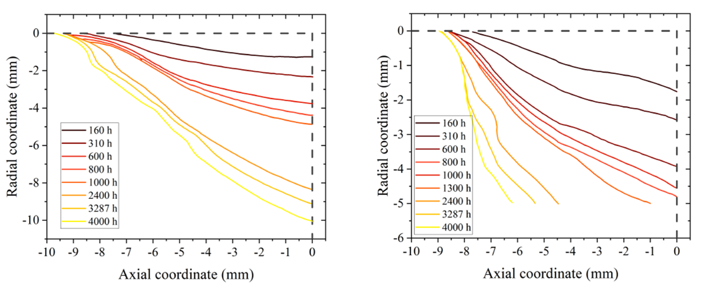
Our first task in the project was to collect erosion data in the form of inner and outer wall erosion profiles for several thrusters over a broad range of sizes and powers (200 W–10 kW). Data about the Russian SPT100 thruster was of course included as this thruster serves as a reference in the field of electric propulsion. Figure 1 shows the erosion profile of the SPT100 wall at 300 V. In our database, Hall thrusters operate with xenon as fuel and have a dielectric channel made of BN or BN-SiO2 ceramics. In this first part we therefore provide examples of computed eroded thickness and erosion rate. Moreover, prediction of thruster lifetime based on experimental data is given and discussed.
In a second step, we accurately defined the sputtering yield and we reviewed models that can be employed to predict the yield as a function of the ion kinetic energy and the ion incidence angle. Finally sputtering yield data often encountered in the literature were described with examples. Inclined readers should be aware that currently yield data only exist for borosil (BN-SiO2) bombarded by singly-charged xenon ions with kinetic energies below 550 eV. Sputtering yield data are necessary to investigate the erosion of the PPS®20k thruster channel wall as the erosion rate is the product of ion current density ji and yield Y.
Electron and ion properties at the wall
Our second main task was purely experimental and consisted in determining the ion flux at the channel wall of the 20 kW-class PPS®20k Hall thruster over a broad range of parameters in terms of applied voltage, gas mass flow rate and input power with atomic propellants. This part is a direct follow up of the previous study as the ion flux is a key factor in the erosion process, hence in the thruster unit lifetime.
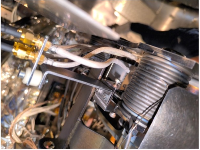
The experimental campaign was performed in August 2025 in the large vacuum chamber VTF – 2 of the Aerospazio Technologie company in Italy with the support of colleagues from both Aerospazio and SAFRAN. The 20 kW-class PPS®20k Hall thruster was equipped with a high-current center-mounted cathode developed by the University of Pisa. The plasma near the outer channel wall of the PPS®20k thruster has been interrogated with planar Langmuir probes inserted into the ceramic and flushed mounted. The probes are placed in the final section of the channel; so they cover the anode and ionization regions. Figure 2 shows the probes and their support.
The thruster was fired with three propellant gases, namely: xenon, krypton and argon. Two sets of four probes separated by 180◦ (opposite side of the annular chamber) and placed at various axial positions in the rear section of the channel have been used. The electron properties were computed from the electron branch (V > Vf ) of the I-V characteristic curve of the probes. The plasma potential decreases when moving towards the anode and approaches the applied minus cathode potential close to the anode. The electron density is larger for xenon and krypton. The electron temperature is larger for argon. These two results originate from the ionization cross-section, which is the largest for xenon. The ion current was computed from the ion branch (V < Vf ) of the I-V curve of the probes. The Johnson and the Sheridan models, which rely and ne and Te values, were employed to correct the raw current traces from the plasma sheath expansion effect with the probe voltage. After correction the ion current density ji at the wall could be estimated. Figure 3 shows the ion branch of the I-V curve for argon in conditions OP1 (299 V, 49.6 A) with and without correction using the Johnson and Sheridan models. The ji value is in the [1 – 20] mA/cm2 range for all propellants, with no clear tendency with the position.
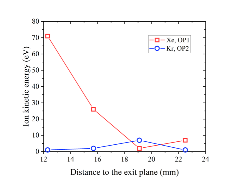
Finally, the Bohm velocity, or ion acoustic speed, and the normal ion velocity were inferred from the electron and ion data. The xenon ion velocity is well above the ion sound speed, meaning the ions flow supersonically towards the wall. For krypton and argon, the Bohm speed and the normal speed are similar. The ion kinetic energy at the channel wall was computed from the perpendicular velocity. Figure 3 shows the kinetic energy of xenon and krypton ions at the wall as a function of the position. Note the anode is located at 30 mm. Interestingly, the energy is much larger for xenon compared to the two other gases. However, for all propellants the kinetic energy remains below the sputtering threshold for BN ceramic in the rear part of the channel. This is certainly one of the main and most important conclusions of this specific work.
Dr. Stéphane Mazouffre
Alexis Lecervoisier
CNRS | ICARE laboratory, Orléans, France